


- Textile Accessories
- Shuttle Loom Parts
- Textile Equipment
- 1511 Textile Machine Parts
- 1515 Textile Machine Parts
- GA615 Shuttle Loom Parts
- Textile Hardware And Tools
- Weaving Machinery
- Textile Auxiliary Equipment
- Loom Picker and Buffer
- Textile Wooden Parts
Repair Tutorial For Warp Protection Components Of Shuttle Looms
This article focuses on the maintenance tutorial of the warp protection components of the 1511 shuttle looms, and the installation process for loom maintenance - ear shaped slider M16 and curved slider rotor rod K10, horn handle I16 and shuttle track rolling shuttle closing, fixed reed nose K23 and collision nozzle K27, etc.
I. Ear shaped skateboard M16 grade ear shaped curved skateboard rotor rod K10 maintenance:
1. The rear end of the ear shaped skateboard rotor rod K10 is 3 millimeters away from the reed seat foot K1 (based on the installation of steel reeds), and the outer side of the rotor rod is roughly flush with the outer side of the reed seat foot K1. The rotor rod is approximately 3 millimeters away from the reed seat cushion iron K83 using hook K11.
2. The gap between the shuttle rod K68 and the pad R28 on the movable back plate is less than 0.2 millimeters, and the sliding plate rotor K847 should rotate flexibly with a lateral movement not exceeding 0.8 millimeters.
3. 1511 loom maintenance bending skateboard support foot M7 kit, installation should be as downward and backward as possible, with the bottom firmly seated and the rear edge vertical.
4. The skateboard rotor K84 and the curved skateboard M16 should be aligned and closely attached to each other. The outer side of the ear shaped skateboard should not touch the wall panel P2, and the inner side should not touch the reed seat foot K1.
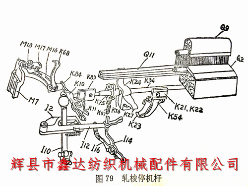
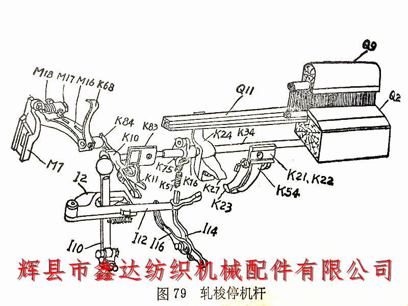
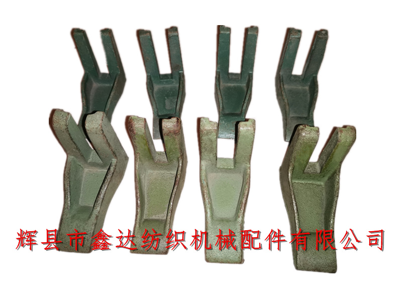
5. The contact time between the ear shaped skateboard and the skateboard rotor should be the same as the shuttle feeding time, and it is allowed to be advanced by 6 millimeters. The high point of the skateboard's curved surface is roughly horizontal to the protrusion on the support foot M7. The up and down travel of the skateboard head is 12-19mm. As shown in the figure below, the elastic force of the M18 bending skateboard spring should ensure that the steel reed does not loosen backwards during the operation of the 1511 loom.
II. Bull horn handle I16 and shuttle track rolling shuttle shutdown maintenance:
1. The horn handle I16 is flush with the head of the rotor rod K10. If the horn handle is slightly inward, it can be filed thin; If it is on the outer side, place a washer of appropriate thickness inside the upright rod I14 and the bristle roller hanging foot L26, or move the rotor rod on the clamp shaft K34 to adjust it.
2. Adjust the left and right positions of the shutdown connecting rod I12 so that the upright rod is located in the middle of the connecting rod groove.
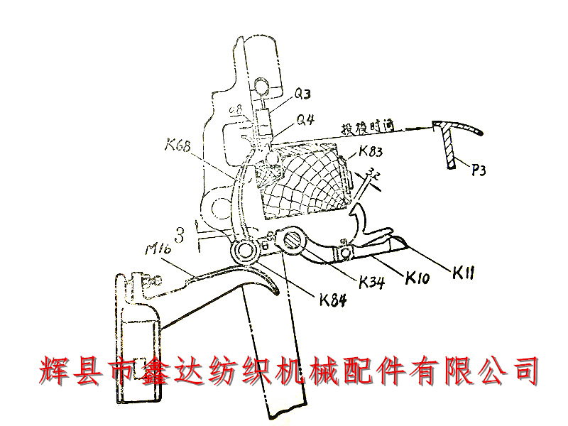
3. Adjust the upper and lower positions of the horn handle: During shuttle rolling, the rotor rod is hooked onto the reed seat cushion iron K83 with hook K11, and the bending shaft is at the front dead center. The front of rotor rod K10 pushes the horn handle I16, and the switch connecting rod I12 slides out of the gap by 1.6 millimeters, as shown in the following figure:
4. After repairing the warp protection components of the 1511 loom, during the test shuttle closing, the rotor rod hook K11 should be hooked onto the reed seat cushion iron K83. Otherwise, the cushion iron can be lowered or the rotor rod K10 position can be raised to adjust it.
III. K23 fixed reed nose and K27 collision mouth:
1. When installing the fixed reed nose (stop switch K23) kit, try to raise the hanging feet K21 and K22 as much as possible, the fixed reed nose core K33 nut should be facing inward, the collision nozzle K27 should be level with both sides of the reed clamp shaft side wing K24, and when the bending shaft F38 is at the front dead center, calibrate the fixed reed nose and collision nozzle to be level with each other.
2. The contact depth between the correction stop pawl and the collision nozzle is 13-16 millimeters. Rotate the bending axis to correct the simultaneous contact between the stop pawl on both sides and the collision nozzle. When adjusting, the front and rear positions of the stop pawl core K33 can be adjusted.
3. Correct the upper and lower gaps between K23 and K27 according to the process specifications, and apply a small amount of butter between them after correction.
When repairing the warp protection components of the 1511 loom, strictly follow the above process (please refer to the 1511 automatic loom maintenance catalog for the marked loom part number), which can reduce the frequency of warp protection failures on small looms and ensure the normal operation of the warp protection components of the loom.
