


- Textile Accessories
- Shuttle Loom Parts
- Textile Equipment
- 1511 Textile Machine Parts
- 1515 Textile Machine Parts
- GA615 Shuttle Loom Parts
- Textile Hardware And Tools
- Weaving Machinery
- Textile Auxiliary Equipment
- Loom Picker and Buffer
- Textile Wooden Parts
Installation And Maintenance Technology Of Broken Weft Self Stop (Weft Fork)
Recently, many customers have inquired about the malfunction of the weft fork - abnormal triggering of the weft fork to stop. Today, we have compiled some information on the installation and maintenance techniques of the loom repair - automatic stop of broken weft fork (weft fork) for everyone to learn and exchange.
I. All components of the warp cutting self stopping device must meet the specifications
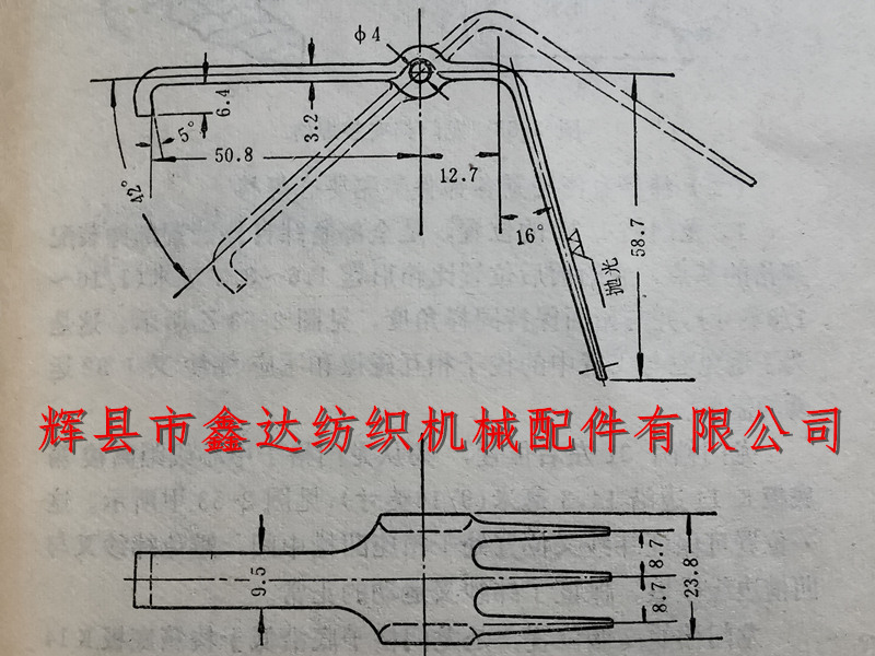
The specification requirements for the J32 weft fork of the weaving machine are: centered around its bolt hole, divided into two parts: head and tail. The three spikes on the head first extend 12.7 millimeters horizontally from the center forward and then bend 74 degrees downwards, with a vertical length of 58.7 millimeters; The tail is a flat body, extending 50.8 millimeters backwards and turning downwards to form a short hook. The hook is 6.4 millimeters long and has a 5 ° angle. The front of the weft fork is 23.8 millimeters wide at the bolt, 9.5 millimeters wide at the flat body, and 3.2 millimeters thick. The center to center spacing of each spike is 8.7 millimeters, and the surface is coated with nickel and polished. When the weft fork is in static equilibrium, it droops at a 42 ° angle due to the tail being heavier than the head. This angle is called the weft fork static balance tail droop angle. Please refer to Figure 2-52 for details.
The basis for determining the elevation angle and length of the J32 weft fork's three spikes is: on the one hand, it is required that when the weft collides with the weft fork, it does not slide into the weft fork; On the other hand, it is required that the weft yarn does not hang the weft fork spikes.
As for the determination of the droop angle at the tail of the weft fork, it is required that when the weft yarn collides with the weft fork, the tail can jump up to an appropriate height. If the tail cannot jump to the appropriate height, it indicates that the tail droop angle is large, that is, the tail is heavier; On the contrary, if the tail jumps too high, it indicates that the tail droop angle is small, that is, the tail is lighter. These problems need to be fixed, because if the tail end of the weft fork jumps too high or too low, it can cause the weft fork to malfunction.
Of course, in the actual production process of the weaving machine, due to the large changes in the tension of the weft yarn, it can also cause abnormal movement of the weft fork. So currently, elastic rubber bands are installed on the support frame behind the weft fork to control the jumping height of the rear end of the weft fork and improve its effectiveness.
2. The gap between the weft fork hole and the bolt should not exceed 0.203 millimeters, and it should be installed in the support frame J18. The weft fork should have almost no lateral movement, but it should also be flexible in rotation.
3. The gap between the support foot J7 of the weft fork rod and the sliding hoop J8 should not exceed 0.203 millimeters at any point, and it is required to slide flexibly.
4. The gantry gear J31 should be smooth, with equal distances between each grid, and the steel wire should be hard and straight without looseness.
5. The angle of the weft hammer hook J2 should be correct, and the gap between the lower hole of the hook and the core J3 should not exceed 0.4 millimeters, and it is required to rotate flexibly.
II. The assembly of each component of the weft yarn self stopping device must meet the specifications
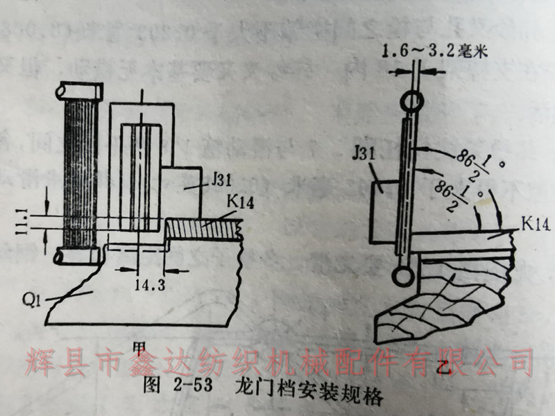
1. The position of the gantry gear J31 is the base point for the assembly specifications of all the components of the warp cutting self stopping device. Its front and rear positions are 1.6-3.2 millimeters behind the steel reed and maintain the same angle with the reed surface, as shown in Figure 2-53B. This is to prevent it from rubbing against the shuttle in flight and to adapt to the movement of the weft fork J32.
The left and right positions of the gantry gear J31 are 14.3 millimeters from the centerline of the gantry grid to the edge of the shuttle box bottom plate K14, as shown in Figure 2-53A. This position ensures that the weft fork is located in the middle of the groove of the reed seat, avoiding the weft fork from rubbing against the edge of the groove and ensuring the normal movement of the weft fork.
The height position of the gantry gear is 11.1 millimeters below the K14 plane of the shuttle box bottom plate at the bottom edge of the gantry grid, as shown in Figure 2-53A, to prevent the weft fork from being installed too high or too low, which may affect the normal activity of the weft fork.
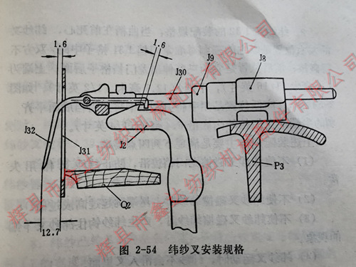
2. The assembly specification of the weft fork J32 is that when the crank is at the front dead center, the left and right positions of the weft fork are aligned with the middle of the J31 grid of the gantry gear with its three spikes, and both sides must not touch or rub. The front and rear positions are such that its three spikes extend behind the J31 grid of the gantry gear, with an upper end of 1.6 millimeters and a lower end of 12.7 millimeters, as shown in Figure 2-54. The high and low positions are achieved by manually pressing down the three spikes to be level with the back of the gantry, with the top of the spikes 6.4 millimeters away from the inner bottom edge of the gantry.

The above assembly specifications mainly meet the following four requirements:
(1) Do not let the weft fork rub against the edge of the gantry to prevent the weft fork from malfunctioning.
(2) Do not let the weft fork collide with the weft yarn, causing the tail end to jump too high or too low.
(3) Do not cause the weft fork to rub against the weft yarn, resulting in the phenomenon of the weft yarn hooking onto the lower end of the weft fork.
(4) When the weft fork moves, the weft yarn will not slide into the fork.
3. The distance between the tail hook of the weft fork and the J2 hook of the weft hammer is when the shuttle flies into the switch side shuttle box and the crank continues to rotate to the front dead center. It is speculated that at this time, the three spikes of the weft fork should jump to the highest point due to the collision of the weft yarn. But in reality, due to inertia, the object always needs to arrive at the above position slightly later than the above-mentioned time. This is why a gap of 1.6 millimeters needs to be left between the tail hook of the weft fork and the J2 hook of the weft hammer when the crankshaft is in the front dead center, otherwise the tail hook will be pulled by the weft fork hook due to not being able to jump up in time, causing the vehicle to shut down.
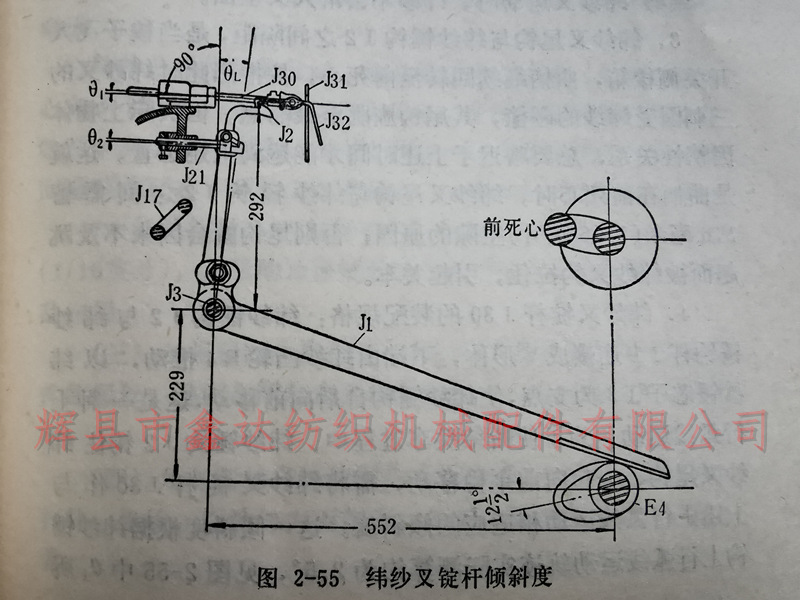
4. Assembly specifications of the weft fork rod J30: The weft hammer hook J2 is connected to the weft hammer hook rod J1 in a V-shape, and the lower end is pushed by the weft cam E4. With the weft hammer core I3 as the fulcrum, the weft hammer hook moves forward from behind, which is an upward curved motion. In order to ensure that the weft hammer hook J2 hooks onto the tail hook of the weft fork and moves smoothly forward during the process of cutting off the weft, the weft fork spindle rod J30 needs to be tilted at an angle that is suitable for the upward curved motion described above. This tilt angle is estimated to be about 2.5 ° based on the actual upward curved motion trajectory of the weft hammer hook, as shown in Figure 2-55, 01.
5. The left and right positions of the weft hammer hook J2 are aligned with the width of the tail hook of the weft fork J32, which results in a larger and smoother contact area when both sides are hooked.
The height position of the weft hammer hook is when the crank is at the front dead center and the shuttle is on the switch side, the weft hammer hook supports the tail hook of the weft fork, so that the flat body at the rear of the weft fork matches the inclination of the weft fork spindle J30.
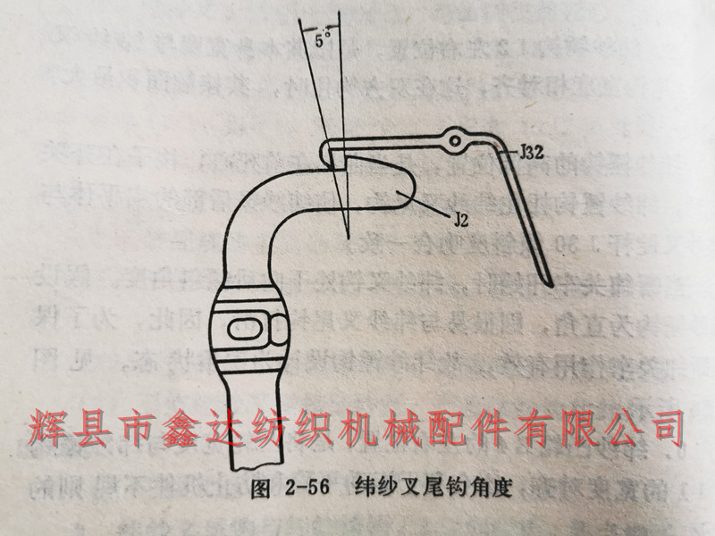
When the cutting and closing of the vehicle starts, the weft fork hook is at a backward tilt angle. Assuming that the weft hammer hook is at a right angle, it is easy for it to slip with the weft fork tail hook. Therefore, in order to ensure the effective function of cutting the weft and closing the car, the weft hammer hook is designed in an acute angle state, as shown in Figure 2-56.
6. The left and right positions of the weft cam E4 align the width of the cam with the width of the weft hammer hook J1, which is beneficial for smooth movement and prevents irregular wear of the machine parts.
The time for the weft cam to act is when the shuttle is on the switch side and the crank moves forward and downward by 25 degrees, causing the large radius of the cam to move forward and making contact between the weft hammer hook J2 and the tail hook of the weft fork J32. After tightening the screws of all relevant components in this way, retract the crankshaft to the front dead center, leaving a gap of 1.6 millimeters between the two hooks.
The gap between the fork wire J38 and the weft fork is 1.6 millimeters, which aims to prevent the disorderly operation of the weft fork during the opening and closing process.
For more information on loom maintenance techniques and knowledge, please follow our company's website.
