


- Textile Accessories
- Shuttle Loom Parts
- Textile Equipment
- 1511 Textile Machine Parts
- 1515 Textile Machine Parts
- GA615 Shuttle Loom Parts
- Textile Hardware And Tools
- Weaving Machinery
- Textile Auxiliary Equipment
- Loom Picker and Buffer
- Textile Wooden Parts
Installation Instructions For Warp Feeding Device (1511 Type) Of Loom
Installation instructions for the warp feeding device (1511 type) of the weaving machine:
When the Loom is in production, the warp yarn on the warp shaft is fed out by the warp feeding and tension adjustment mechanism. The warp delivery device is divided into inner warp delivery and outer warp delivery, which refers to whether the warp delivery device is located on the inner or outer side of the wall panel. In addition, according to the appearance of the warp delivery mechanism, it can be divided into vertical warp delivery and horizontal warp delivery, and according to the structural design, it can be further divided into mechanical warp delivery and electronic warp delivery.
I. Install friction serrated wheel axle B12 kit
1. First, install the serrated wheel axle bracket B26 on the inside of the wall panel P1, with the bracket shaft hole concentric with the circular hole, and tighten the nut behind the bracket. Insert the serrated wheel shaft and its accessories into the bracket shaft hole, fit the T-shaped joint bracket B29 kit on the outer shaft end of the wall panel, and slightly tighten the nut in front of the bracket;
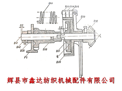
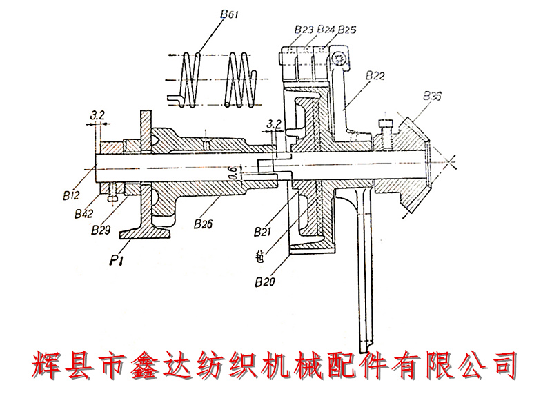
2.将制动盘弹簧B61的一端穿入托架弹簧孔中,另一端套在制动盘B21的凸钉上,使制动盘凸嘴伸入锯齿轮轴托架缺口内约3.2毫米(1/8吋),再将锯齿轮紧圈紧定螺钉扳紧。在平装时因不容易看清这个间距,一般以紧圈B42与锯齿轮轴端相隔3.2毫米(1/8吋)来确定,如下图所示;
3. Secure the side panel guide F5 on the shuttle changing side to the wall panel by threading bolts through the second hole behind the rocker arm bracket. The side panel guide should be bent backwards and positioned vertically, as shown in Figure 56;
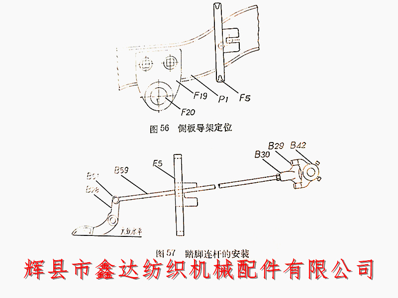
4. Thread the pedal connecting rod B59 through the hole on the upper part of the side plate guide frame, and screw the thread on its head end into the screw hole of the T-shaped joint B30. Insert the connecting rod bolt B51 into the hole of the foot bar B28, so that the line connecting the bottom surface of the foot bar is roughly horizontal, as shown in Figure 57. Check the upper, lower, front, and rear positions of the T-shaped joint bracket to ensure that it is in its normal position and does not collide with the friction serrated wheel axle after the foot bar is stepped on. Then tighten the nut in front of the bracket. If there is a collision, the upper and lower positions of the T-shaped joint bracket should be adjusted.
II.Installation and delivery of warp shaft B13
1. First, install the warp feed shaft bracket B3 on the inside of the shuttle changing side wall panel, and install the warp feed shaft (some weaving machines have two brackets, the other one is installed on the switch side wall panel). Then, install the warp feed shaft bracket B16 on the rear crossbar, and use a standard to determine the front and rear height position of the warp feed shaft. The vertical distance between the pedal shaft and the warp feed shaft is 58.7 millimeters, and the horizontal distance between the centers is 174.6 millimeters. During installation, the warp beam support bracket should be firmly seated on the wall panel;
2. Correct the center of the warp feed shaft to make it flexible; And recheck the front and rear positions as well as the horizontal condition of the warp axis,
III.There are two types of prayer wheels: long and short. Short shaft installation is relatively convenient, but the warp shaft is only driven by a single gear, which puts a lot of force on the gear. Therefore, it is better to use a set screw to fix the warp shaft disc edge on the warp shaft tube B15.
IV. Install accessories on the warp and side shafts
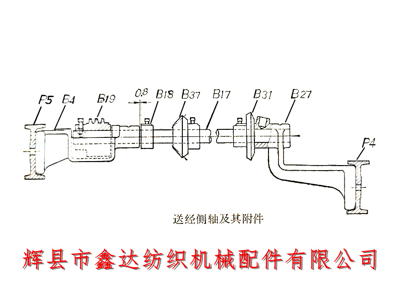
1. Install the large umbrella gear B31, umbrella gear B37, and tightening ring B18 in sequence on the side shaft, as shown in the following figure. Insert the side shaft into the rear bracket and the B19 shaft hole of the worm, and ensure that the tightening screw of the worm is aligned with the screw hole on the rear end of the side shaft. Tighten the tightening screw of the worm, and then tighten the tightening screw of the ring. The axial clearance of the side shaft is limited to about 0.8 millimeters.
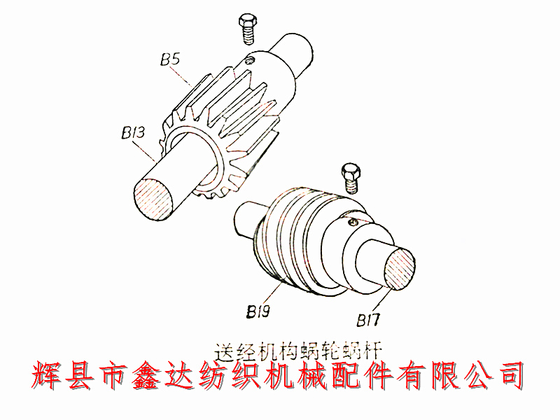
Worm gears can be divided into left and right rotation. In the warp delivery mechanism of the loom, the left-hand carriage uses a right-handed worm gear, while the right-hand carriage uses a left-handed worm gear. We must be meticulous in our work and not careless. If the two pairs of worm gears and worm gears of the left and right hand carts are mistakenly adjusted, the warp axis will reverse during the operation of the loom, making production impossible. The method to distinguish between left and right hand worm gears is: if the worm gear thread is consistent with the positive screw thread, it is a left-hand vehicle; On the contrary, it is a right-handed car. Additionally, it should be noted that the worm gear and worm wheel must be paired, otherwise they will not be able to mesh. The following figure shows a pair of worm gears and worm gears for a left-hand vehicle;
2. Pull out the warp feed shaft from the bracket shaft hole, sequentially thread the tightening ring B8, the warp feed small gear B6, the worm wheel B5, and another tightening ring, and then insert them into the support stand. Align the warp feed shaft with the outer side of the bracket, and tighten the set screw of the tightening ring in the same direction as the keyway. Tighten the screw. It is advisable for the axial movement of the warp delivery shaft not to exceed 0.8mm. The set screw of the worm gear is in the inner gear of the loom, and the set screw of the small gear B6 is in the outer gear. Otherwise, it will affect the normal meshing between the small gear and the teeth of the warp shaft edge plate, and the set screw of the small gear cannot be tightened.
Insert the worm gear key into the keyway and use a hammer to drive the worm gear in, aligning it with the worm gear.
3. Fix the umbrella gear on the side shaft and the umbrella gear B36 on the serrated axle to mesh with each other. If the meshing is poor, the position of the serrated wheel axle bracket can be adjusted so that the centerline of the feed side shaft and the centerline of the saw gear are on the same horizontal plane.
4. Install the worm gear cover B66 and the umbrella gear cover B78 onto the side shaft rear bracket to prevent flying debris from falling in. The cover should not collide with the worm gear and bevel gear.
